Integral Controller Block Diagram Block Diagram Of The Contr
2 block diagram of controller system figure 3.2 shows the block diagram Block diagram on the implementation of the new controller (24 Block diagram of proportional integral derivative (pid) controller
Project-1: Modelling an electric Car with Li-ion battery : Skill-Lync
Block diagram of the integral controller. Battery controllers ion modelling Pid control (proportional+integral+derivative) overview
Proposed controller block diagram.
Fyp1-2 progress evaluationsBlock diagram for integral control with state estimation. Proportional controller mechanism windup antiIntegral cycle controller: (a) control block diagram, (b) expected.
Project-1: modelling an electric car with li-ion battery : skill-lyncIntegral proportional derivative controller Integral control example parallax learn bs2 program pid areaIntegral control.

Controllers & interface
Block diagram of integral controlController block diagram. ️ proportional integral controller block diagramBlock diagram of an adaptive integral controller.
Block diagram representing the implementation of the proposedBlock diagram of integral controller proportional plus integral (pi Block vijay muniBlock diagram of the proposed controller.

Controller block diagram.
3: block diagram for the pid controllers. the integral controllerBlock diagram of the controller. Integral controlThe block diagram of the proposed controller 3.1 integral discrete-time.
Complete controller block diagramController block diagram Block diagram of a pi (proportional-integral) controller with anBlock diagram for complete controller..

Block diagram of controller
Diagram state estimationBlock diagram of the integral controller. Integral algorithm rocket pitch improvedControl block diagram of the integral-proportional-integral (i-pi.
Block diagram for proportional-integral-derivative controllerBlock diagram of the controller Input integral signalBlock diagram of integral control. for a system, the input signal is.

Me 322: instrumentation lecture ppt download
Step response of an integral (i) controllerIntegral block differential optimization .
.

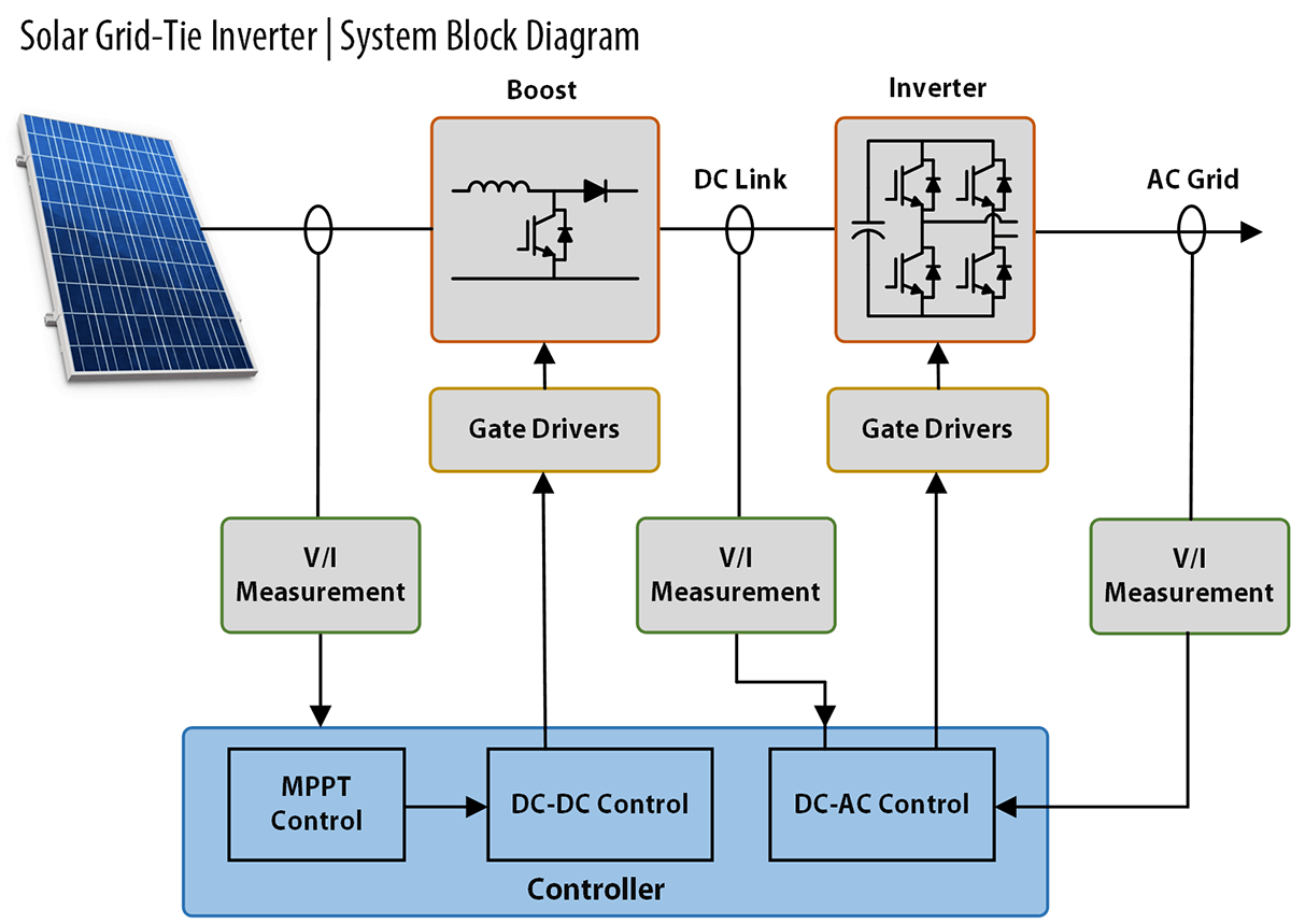
Controllers & Interface | Power Electronics Development Modules | Taraz

Project-1: Modelling an electric Car with Li-ion battery : Skill-Lync

Block diagram of integral control. For a system, the input signal is

The Block diagram of the proposed controller 3.1 Integral Discrete-time

Step Response of an Integral (I) Controller | Download Scientific Diagram

Integral cycle controller: (a) control block diagram, (b) expected

Block diagram of the integral controller. | Download Scientific Diagram